System equipment carrier

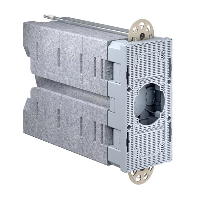
Modular support for devices 240 – 310 mm

Modular support for devices 240 – 310 mm
Preview: Modular support for devices 240 – 310 mm Preview: Modular support for devices 240 – 310 mm
   
Modular support for devices 240 – 310 mm
  • 9966.12
  • 372900919
  • 7611614268736
  • compatible with Feller SNAPFIX®
  • can be reduced by 70 mm in 10 mm steps
Material
PE-HD
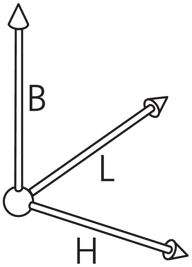
Length
110 mm
Width
220 mm
Height
240-310 mm
Combination conduit entries M20/25
2
Combination
1x1 / 2x1 / 3x1 / 2x1 NUP
Screw-in wall-plug
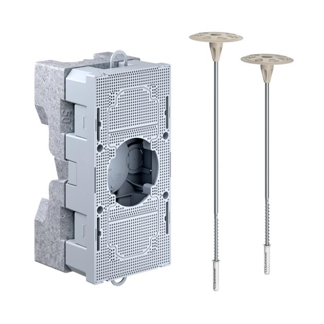
1x280 mm / 1x320 mm
Dispatch
5
Product information

System equipment carrier

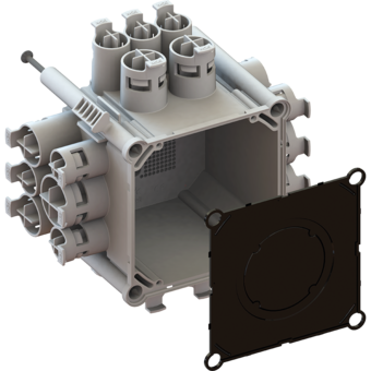
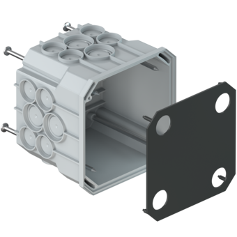
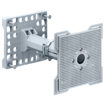
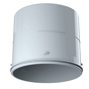
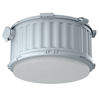
Modular support for securely attaching electrical installations in or to heat-insulating external facades. Stable attachment of external lights, sockets, motion detectors, external temperature sensors, radio receivers, anemometers, cameras, letter boxes and much more.

  • compatible with Feller SNAPFIX®
  • Quick fastening with screw-in wall-plug_x000D_
  • 2 Produkttypen ermöglichen 6 Anwendungen
  • In 10 mm-Schritten an Dämmstärke anpassbar - Zuschneiden entfällt
  • Prevents heat bridges
  • für Dämmstärken von 160 bis 310 mm
  • Can be attached on surfaces made of concrete, bricks, wood, OSB, MDF, gypsum fibreboard etc.
  • Easy disassembly

Examples of use

Auslieferstatus Öffnung Ø 73 mm, 1x1

Kombination 2x1 NUP (2 Abdeckungen ausbrechen)

Kombination 3x1 (2 Abdeckungen ausbrechen)

mit ausgebrochenem Auslass für Leuchten

Weight-bearing loads

1 Weight-bearing loads – independently of the insulation thickness: For an overhang of 160 mm and insulation thicknesses of 160 - 310 mm; 8 kg without additional screwing of the front plate; 10 kg with additional screwing of the front plate. The system equipment carrier must be fitted vertically. The hole for the dowel must be drilled to make an exact fit. | 2 Increasing the weight-bearing loads: To fix heavier loads, we recommend additional securing of the mounting plate by means of four Ø 3.5 x 25 screws

Installation

Backsteinmauer mit Rohraustritt.

Geräteträger durch die passende Wahl von Bauteilen an Dämmstärke anpassen.

Bohrtiefe mindestens 60 mm.

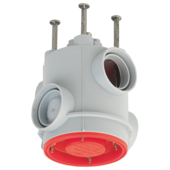
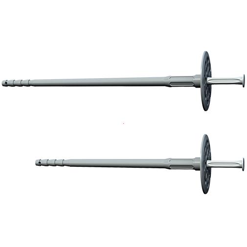
Remove the side lugs from the impact dowel. Note the different lengths!

Depending on the length of the dowel, it must protrude from the equipment carrier by at least 30 mm.

Hold the equipment carrier against the wall, align it, and fix it using the dowel.

Press the conduit into the side guide and cut it to length.

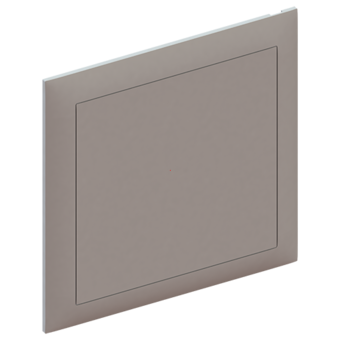
Gewünschtes Frontteil aufklicken. Styroporstopfen eindrücken. Die Rohrenden werden abgedeckt.

Combinations with front panels

Auslieferstatus 9966.11 und 9966.21., Öffnung Ø 73 mm, 1x1

Kombination 2x1 (1 Abdeckung ausbrechen)

Kombination 3x1 (2 Abdeckungen ausbrechen)

Kombination 2x1 NUP (2 Abdeckungen ausbrechen)

Die ausgebrochenen Kunststoffflächen können an der perforierten Stelle mit dem Messer zugeschnitten werden und...

...zur Ordnungstrennung in Kombinationen 2x1 und 3x1 eingesetzt werden.

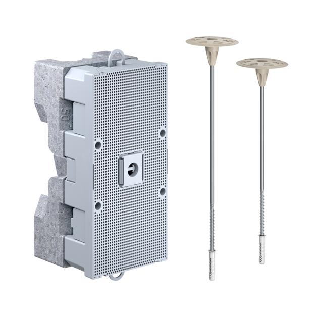
Auslieferstatus 9966.12 und 9966.22, Universal Montageplatte

mit ausgebrochenem Auslass für Leuchten

Tips and tricks

Für ein zusätzliches Rohr können die Stege bei den Neoporteilen entfernt ...

… and the perforated entry broken out in the case of the dowel cover

Für die Befestigung grosser Lasten empfiehlt es sich, die Montageplatte mit Schrauben M3.5x25 zusätzlich zu sichern.

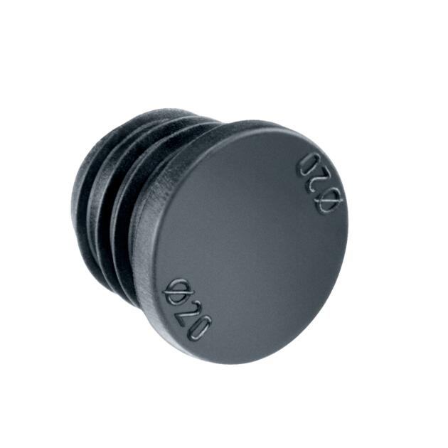
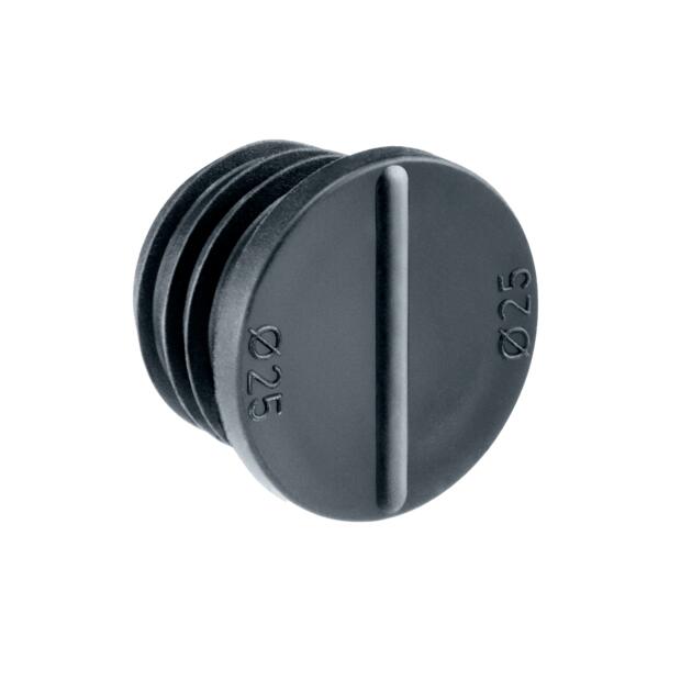
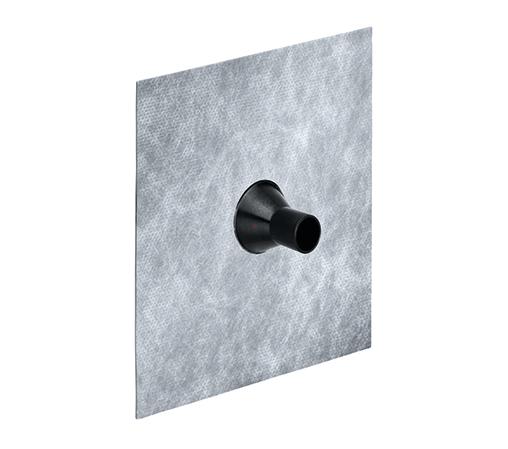
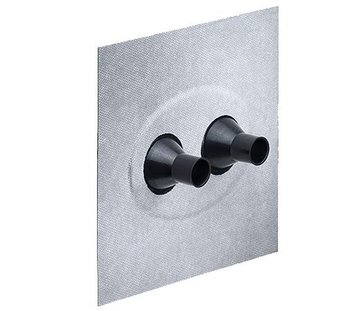
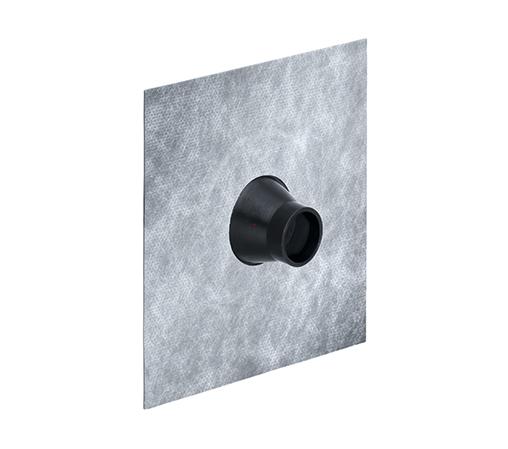
Für eine luftdichte Installation muss die Rohr-Austrittsstelle mit einer geeigneten Luftdichtmanschette und das Rohr mit einem Dichtstopfen versiegelt werden.

For insulation thickness < 160 mm, order product 9966.11 or 9966.21...

... remove as many elements as necessary until the appropriate insulation thickness (min. 100 mm) is achieved.

Passenden Schlagdübel bestellen (E-No. 165 151 100 / 100 - 130 mm) (E-No. 165 151 500 / 140 - 170 mm)

... oder den passenden Schraubdübel (E-No. 165 151 400 / 100-130 mm) (E-No. 165 151 800 / 140-170 mm) bestellen.

Heat bridge calculation

A heat bridge calculation carried out by the Passivhaus Institut in Darmstadt shows that the system equipment carrier has a point-specific heat bridge loss coefficient of xWB < 0,01 W/K and meets the requirements of a heat bridge-free facade.

Download
Product data sheet

Modular support for devices 240 – 310 mm

Article no: 9966.12

Download
Leaflets

System equipment carrier.

For electrical installation without thermal bridges. Leaflet available in German, French and Italian.

6.9 MB | 2020-01-14