


Fire-stop box FlamoX®
FlamoX® fire-protection putty
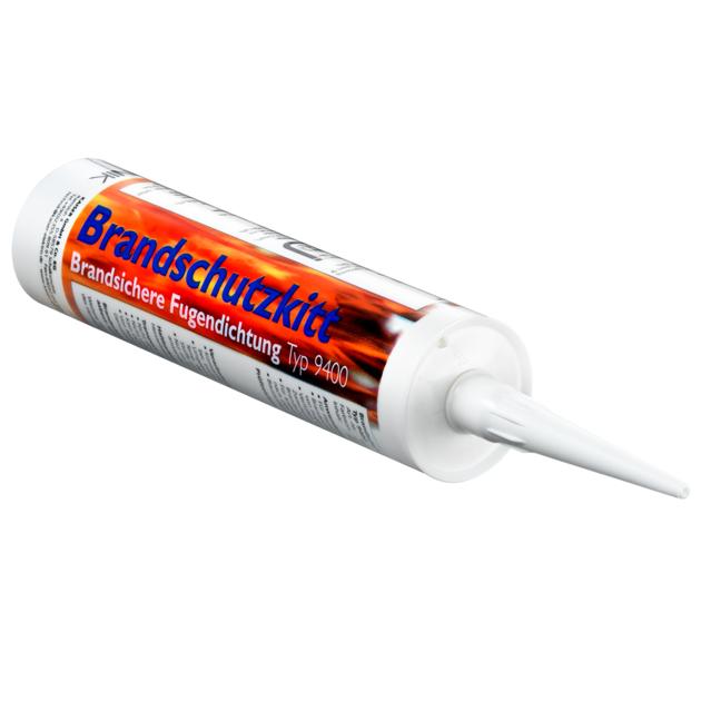

- Article no: 9400-05
- E no.: 920898009
- EAN: 4013456461611

- Building material forming an insulating layer
- for filling joints as well as bonding board materials
- Type 9400
- Working time 30 mins.
- Can be stored up to 12 months
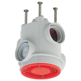
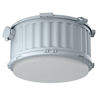
Fire-stop box FlamoX®
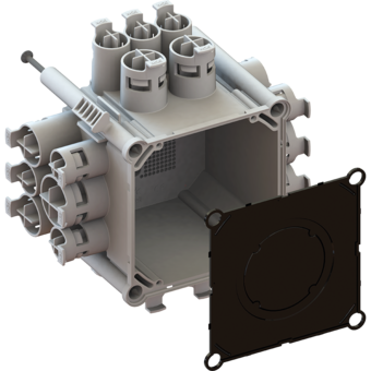
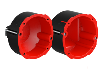
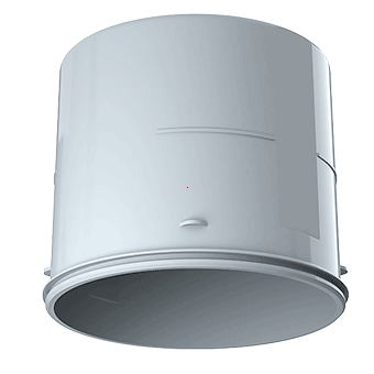
FlamoX® installation housings for luminaires and loudspeakers protect lives and material goods if a fire breaks out. In luminaire and loudspeaker installations in fire-protection ceilings, the integrated fire-retardant coating gives the housings the fire-protection class F30 (EI30) of the ceiling. They prevent fire and flue gases from spreading, so they secure escape routes in buildings. FlamoX® fire-protection housings provide certified security.
- Safe, certified fire-protection housings for built-in luminaires and loudspeakers
- Fast, easy fitting from the underside of the ceiling
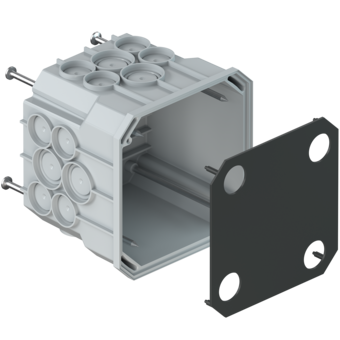
- Suitable for fire resistance from above and below
- Installation without additional suspension
- No use of additional fire protection materials or sealing compounds
- DIBt approval Z-19.11-1583


Functioning of the fire-retardant coating in the event of fire (fire load from below)


Functioning of the fire-retardant coating if a fire breaks out (fire load from above)


Examples of use


Note
FlamoX® housings are tested fire-protection housings for the fire-protection sealing of built-in luminaires and loudspeakers in independent, two-layer suspended F30 fire-protection ceilings made of plasterboard fire-protection panels with or without insulation. The ETA-certified (European Technical Assessment) housings are approved for fireloads from above and below. The FlamoX® housings were tested according to DIN EN 1363-1 and DIN EN 1366-3, so they can be installed in ceiling systems which were built according to DIN 4102-4 or DIN EN 1364-2 or have certification in the form of a general building approval certificate.
Technical information


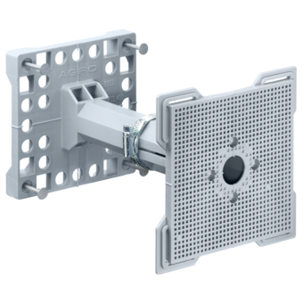
Installation


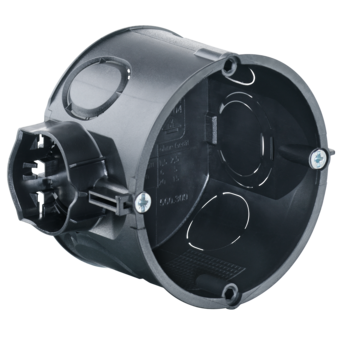
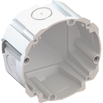
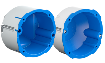
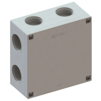
Retrofitting in installation shafts
The HWD 90 cavity wall boxes can also be retrofitted in installation shafts (shaft walls). Since retrofitting partly requires adding mineral wool to the opening, a cut-out of at least 300 x 300 mm is needed to make space for perfect installation. Use the following cut-out dimensions for the relevant combinations:
- 1-time: 300 x 300 mm
- 2 to 3-times: 300 x 400 mm
- 4 to 5 times: 300 x 600 mm